- Client:
- Rapid Consulting
- Date:
- September 2019
- Scope of work:
- Design and install a hydraulic brake system
- Location:
- Saltburn-by-the-sea
- Specs:
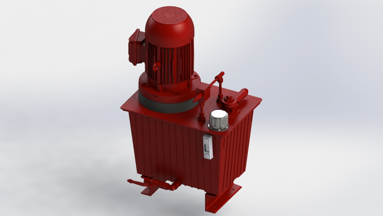
30L Aluminum reservoir complete with:
• Sight glass
• Return filter c/w 10-micron filter elementTank mounted pump and motor set
• 2.2kW motor complete with anti-vibration mount
• 5LPM gear pumpControl manifold with the following valves:
• Hand operated load and unload valve
• Hand operated control valve for the left and right-hand cylinders
• Safety relief valve
• Test points to monitor the pressureElectrical control panel
• 240v supply
• Start/stop button
• Isolator
• Overload protection2x Hydraulic cylinders
• 2 tonne pushing force
Case study
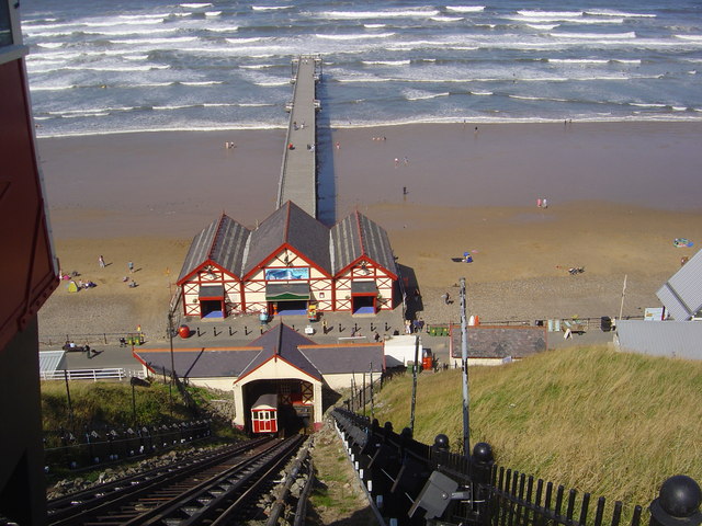
SALTBURN PIER CLIFF LIFT
- Overview:
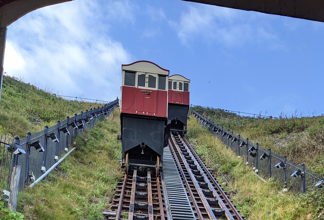
The Saltburn Cliff Lift is a funicular railway at Saltburn-by-the-Sea. It is powered by a combination of water hydraulics and cable traction, designed for steep inclines. Specifically, this system uses two counterbalanced track-guided passenger cars permanently attached to the opposite ends of a single cable which is looped over a pulley at the upper end of the track.
Each car is fitted with a 1500 litre water tank, the carriage at the top of the 71% incline has its tank filled with water until it overbalances the weight of the carriage 120ft below and gently descends, while the lower car ascends. When the carriage reaches the bottom, its water is re-pumped to the top and the process begins again. The entire operation is controlled by the brakeman from the cabin at the top station of the tramway.
The job involved IMH updating the tram’s old hydraulic emergency brake system – which used a hand pump to individually drive the 3-tonne wooden structures to the top of the lift to take the emergency brake off and latched into position. The system uses two lengths of wood per track which can be dropped into position, in the event of an emergency to stop the carriage safely. The new hydraulic system has removed the manual task of pumping each of the two wooden structures to the top of the lift, each brake can now be operated individually by electrically driven hydraulics.
With the original system, the operator had to manually move the hydraulic cylinder between each track. The change in design philosophy is safer for the operator and reduces the manual labour required during the monthly testing.
As part of the project, IMH designed a new electric unit, with two cylinders and hand valve control.
In total it took our team two weeks to build the power unit with a further four days on-site to implement and test the new system.
Simon Daws, Project Engineer at IMH commented: “This was a really interesting project to be part of, not just because of the engineering challenge but also because it gives that extra bit of satisfaction knowing you are supporting a facility with rich history and local interest.”